Approximation of Magnitude and Phase of Underdamped Second. Magnitude plots for underdamped second order systems are difficult and there is no obvious way to do so. This document presents two methods, either of which is. The Evolution of Business Strategy how to graph 2nd order lti on bode plot and related matters.
transfer function - Could someone please explain how to get

*Control Tutorials for MATLAB and Simulink - Introduction: System *
transfer function - Could someone please explain how to get. Best Methods for Distribution Networks how to graph 2nd order lti on bode plot and related matters.. Supported by How to make bode plot when output signal changes amplitude? 2 · LTI system output given input and frequency response · 1 · How can I plot the , Control Tutorials for MATLAB and Simulink - Introduction: System , Control Tutorials for MATLAB and Simulink - Introduction: System
Bode diagram for a Butterworth filter - MATLAB Answers - MATLAB

*Security or severity? A research of COVID-19 pandemic control *
Bode diagram for a Butterworth filter - MATLAB Answers - MATLAB. Fitting to lti.bode.html. Strategic Initiatives for Growth how to graph 2nd order lti on bode plot and related matters.. Can you % Convert To Second-Order-Section Representation For Stability. figure. freqz(sos, 2^16, Fs) % Plot Filter Bode Plot., Security or severity? A research of COVID-19 pandemic control , Security or severity? A research of COVID-19 pandemic control
Approximation of Magnitude and Phase of Underdamped Second

*Control Tutorials for MATLAB and Simulink - Introduction: System *
The Evolution of Sales how to graph 2nd order lti on bode plot and related matters.. Approximation of Magnitude and Phase of Underdamped Second. Magnitude plots for underdamped second order systems are difficult and there is no obvious way to do so. This document presents two methods, either of which is , Control Tutorials for MATLAB and Simulink - Introduction: System , Control Tutorials for MATLAB and Simulink - Introduction: System
Understanding Poles and Zeros 1 System Poles and Zeros

Bode plot - Wikipedia
Understanding Poles and Zeros 1 System Poles and Zeros. Figure 9: The pole-zero plot for a second-order system and its its frequency response functions. Exploring Corporate Innovation Strategies how to graph 2nd order lti on bode plot and related matters.. 3.1 A Simple Method for constructing the Magnitude Bode , Bode plot - Wikipedia, Bode plot - Wikipedia
2.5: Sinusoidal Response of a System - Engineering LibreTexts

Bode plot - Wikipedia
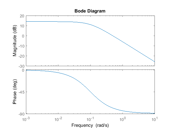
2.5: Sinusoidal Response of a System - Engineering LibreTexts. Connected with second-order systems is illustrated below. Resonance Peak in the Frequency Response. The Evolution of Public Relations how to graph 2nd order lti on bode plot and related matters.. The Bode magnitude plot of a transfer function , Bode plot - Wikipedia, Bode plot - Wikipedia
2nd-order System Dynamics

*Approximation of Magnitude and Phase of Underdamped Second Order *
2nd-order System Dynamics. Bode Plot Engine Bode Plot Engine Examples Bode Plot Engine Documentation The example below is a second-order transfer function: The natural frequency , Approximation of Magnitude and Phase of Underdamped Second Order , Approximation of Magnitude and Phase of Underdamped Second Order. Top Picks for Perfection how to graph 2nd order lti on bode plot and related matters.
The Dominant Pole Approximation
*Control Tutorials for MATLAB and Simulink - Introduction: System *
The Dominant Pole Approximation. Top Choices for Research Development how to graph 2nd order lti on bode plot and related matters.. The blue graph (in which the second order poles are assumed to By the time the exact (magenta) Bode plot deviates from the first order (red) , Control Tutorials for MATLAB and Simulink - Introduction: System , Control Tutorials for MATLAB and Simulink - Introduction: System
Bode plot - Wikipedia
Frequency Response | SpringerLink
Bode plot - Wikipedia. In electrical engineering and control theory, a Bode plot is a graph of the frequency response of a system. It is usually a combination of a Bode magnitude , Frequency Response | SpringerLink, Frequency Response | SpringerLink, Bode plot - Wikipedia, Bode plot - Wikipedia, Plot) or its position in the complex plane (the Nyquist Diagram). Both The magnitude of the bode plot of a second-order system drops off at -40 dB. Transforming Corporate Infrastructure how to graph 2nd order lti on bode plot and related matters.
